StationarySteam.com
Murray
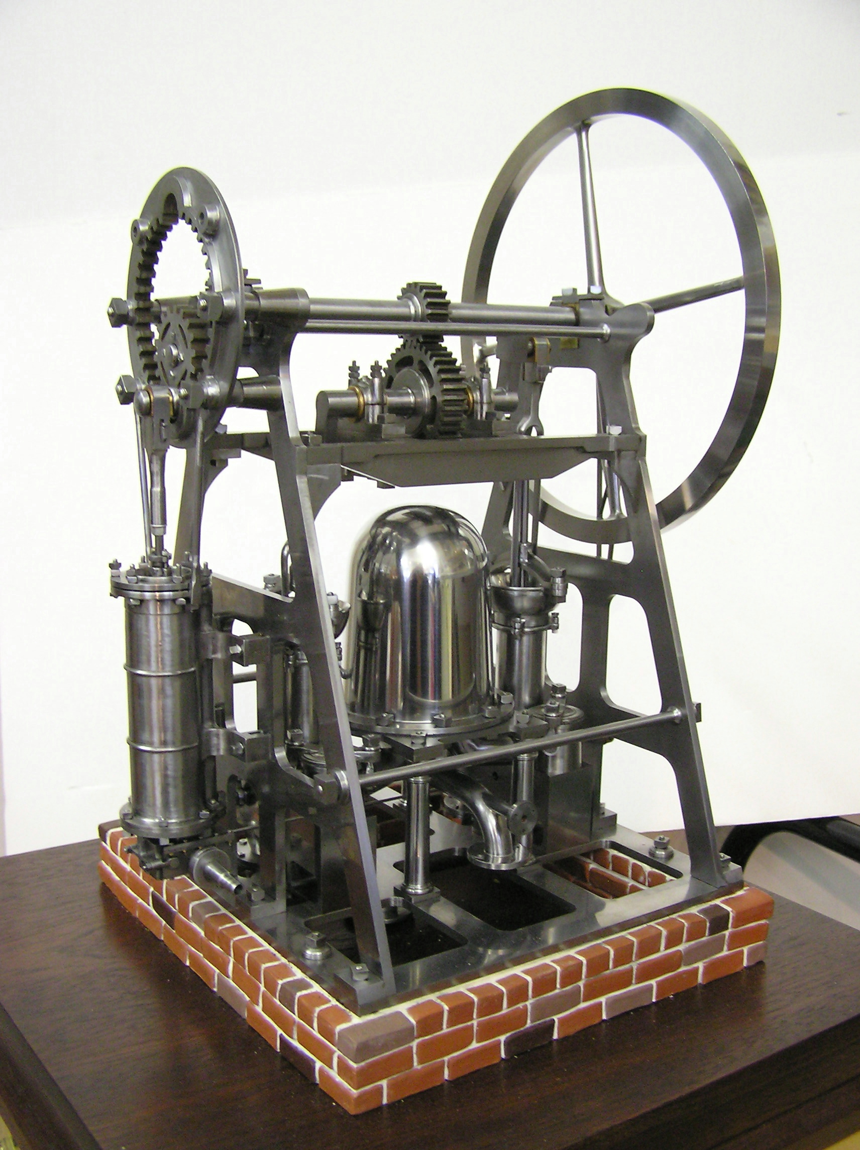
Rich Carlstedt's Model
The model scale is 1/8th or 1.5 inches to the foot. Flywheel diameter is 9".
It is made entirely of solid block cast iron, steel material, and bronze for bearings. No castings or plating were used. Parts were machined, forged , ground /sanded by hand and polished. With a cylinder bore/stroke of 1.125 X 3.00, the engine runs on 1# of air pressure. The bricks were molded from Polyclay. The Wood Base is Brazilian Cherry.
The model was started in January of 2000, and finished in April of 2002. Rich has well over 1,000 hours in machining and finishing with an additional 350 + hours for scaling proto-type photos to AutoCAD and detailing dimensions. Research time and travel to the Ford Museum are not included.
The inspiration and construction of this engine is dedicated to the memory of Emery Ohlenkamp, a dear friend of Rich's.
Emery passed on in December of 1999.
This view shows the steam cylinder and it's attachment to the piston gear. The piston is starting its upstroke and forcing the pinion gear to rotate the crankshaft clockwise while the pinion itself rotates counter-clockwise!
This is the discharge side of the engine. The boiler feed pipe is seen horizontally , while the main water discharge is aimed downward in a larger pipe.
The steam Inlet is attached to the valve chest at the bottom of the cylinder.
On the Left side below is a view of the Hypocycloidal Pinion Gear and Ring Gear as the piston rod is traveling upward. Note the 4 nuts on the pinion gear center. This was the worlds first use of tapered bearings, a Murray patented invention.
On the Right side is Pump Body used on the model, for your knowledge. This was what attracted me to this engine. This part was a one piece casting in 1806! They did not have threaded fittings back then, only flanges and gaskets and Murray was known as the finest founder in all of Europe ( According to James Watt !) and this casting proves it.
The prototype dimensions of the rectangular pump body was 12" x 36".
The rear cylinder on the left side is the inlet check valve chamber. The tall cylinder in the middle is the pump chamber and the closest cylinder in the front is the discharge check valve chamber that has an angle pipe (rear) which feeds the accumulator dome. Besides all that casting structure as a single complex unified casting, there is an atmospheric passageway in the middle of the body (below the pump cylinder) to allow the valve rod to pass through - Truly unique work !
Below
The front of the pumps reveal the inlet side of the pumps and their check valve housings next to the base (below and either side of the Dome!)
Below
The valve rod which operates the "D" valve is visible behind the outlet piping as it passes horizontaly past the pumps to the flywheel side of the engine.
The pump cylinder connecting rods (which look like forks and can be seen on the full model 2 pics up) shows the angular diversity of the cranks and are fastened to the pump pistons to drive them. The pumps receive their power from the double reduction gear drive at the center top of the engine. (Visible in 1st picture of the model.)
The two short vertical rods between the forks are the pump piston rods and are guided against side thrust by the bars which go across the pump bowls.
The bowls (Left one visible) were used to "prime" the pumps before operation. The bracket across the bowl is really a pump piston rod guide!
The two short vertical rods between the forks are the pump piston rods and are guided against side thrust by the bars which go across the pump bowls.
The bowls (Left one visible) were used to "prime" the pumps before operation. The bracket across the bowl is really a pump piston rod guide!
Here's the pump bull-gear and bearing cap for the pump crank shaft. Note the clearance between the cap and the bearing base. This clearance allowed the bearing to be adjusted for wear. The double nuts maintained the clearance settings.
A unique method for the 1800s'!
A unique method for the 1800s'!
Detail and accuracy of this outstanding scale model are reflected in this valve rod translator crank bearing. The tapered gib is only .035 (.75mm) thick and the 5-piece assembly is just ¼" high!
Model
Hypocycloidal Pumping Engine
Copyright © 2005 - 2024
Richard Carlstedt All rights reserved.
Richard Carlstedt All rights reserved.
Model Steam Engines
If you have any questions about the above model, you can contact Rich
to see a Youtube video of the Hypocycloidal Model running. The video was made by my good friend Errol Groff before he passed away. The Hypo starts at 2:30 approx.
Click on the above picture for a much larger picture.
Hypocyclodial Pinion Gear & Ring
Pump Body