StationarySteam.com
The Vibrating Lever 1/2 Trunk Steam Engine
of the
of the
U.S.S. Monitor
Click on any thumbnail to see a screen filling, high quality, image.
Use your "back" button to return to this page.
Use your "back" button to return to this page.
Toward Stern
and above. |

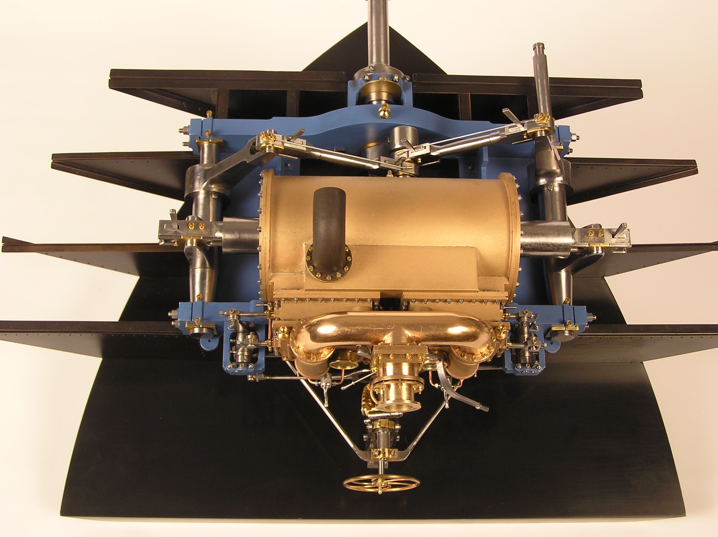
From Stern
and propeller |
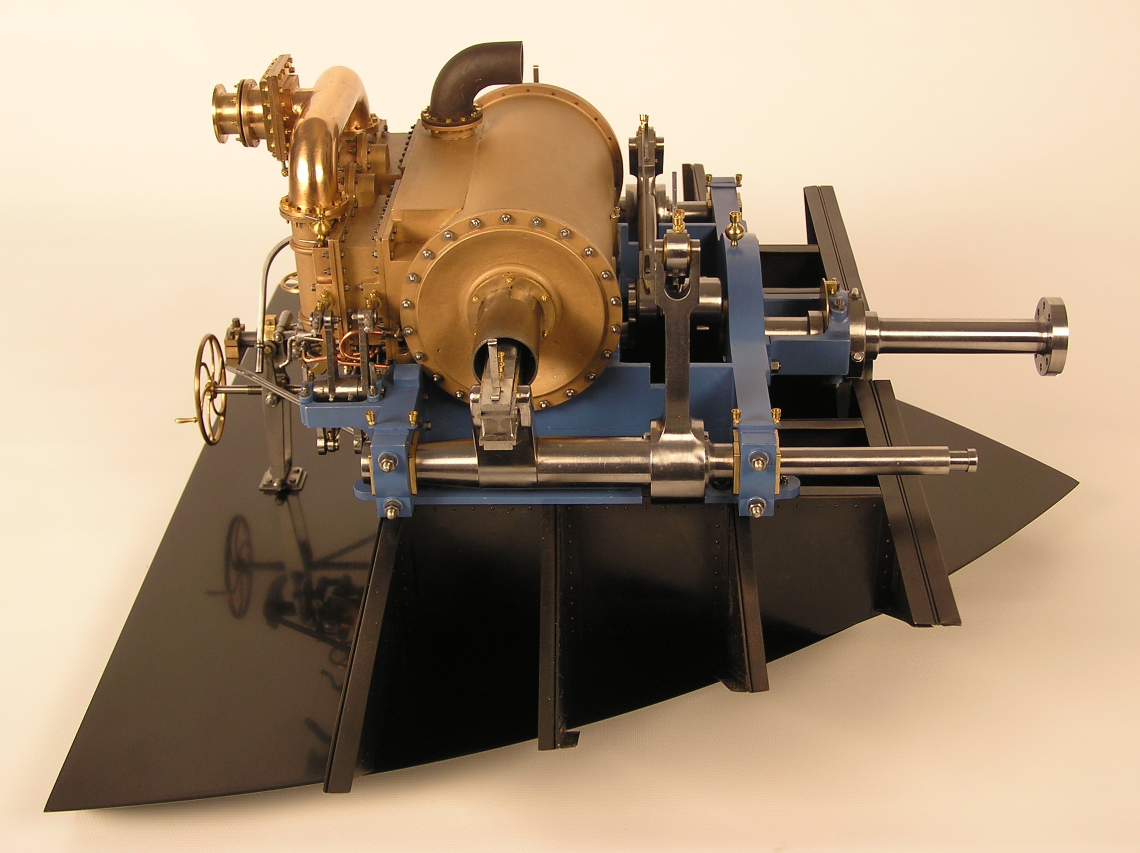
Engine
Port side |
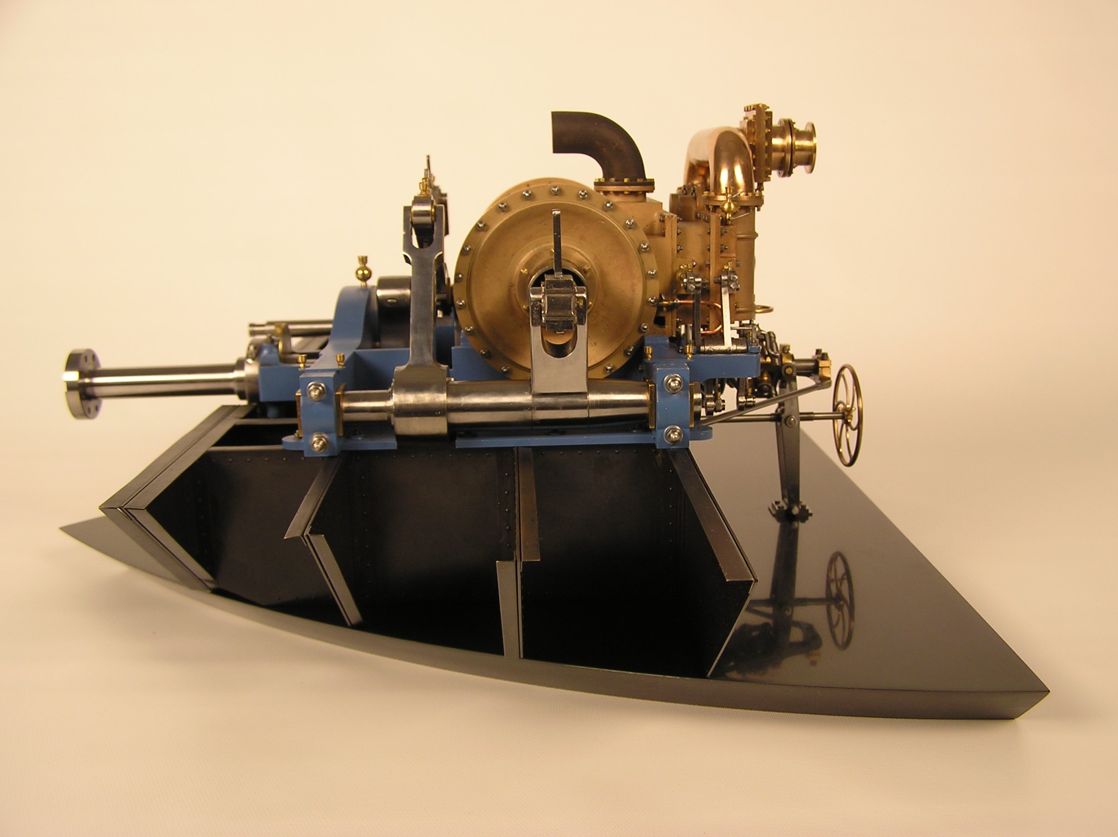
Engine
Starboard side |
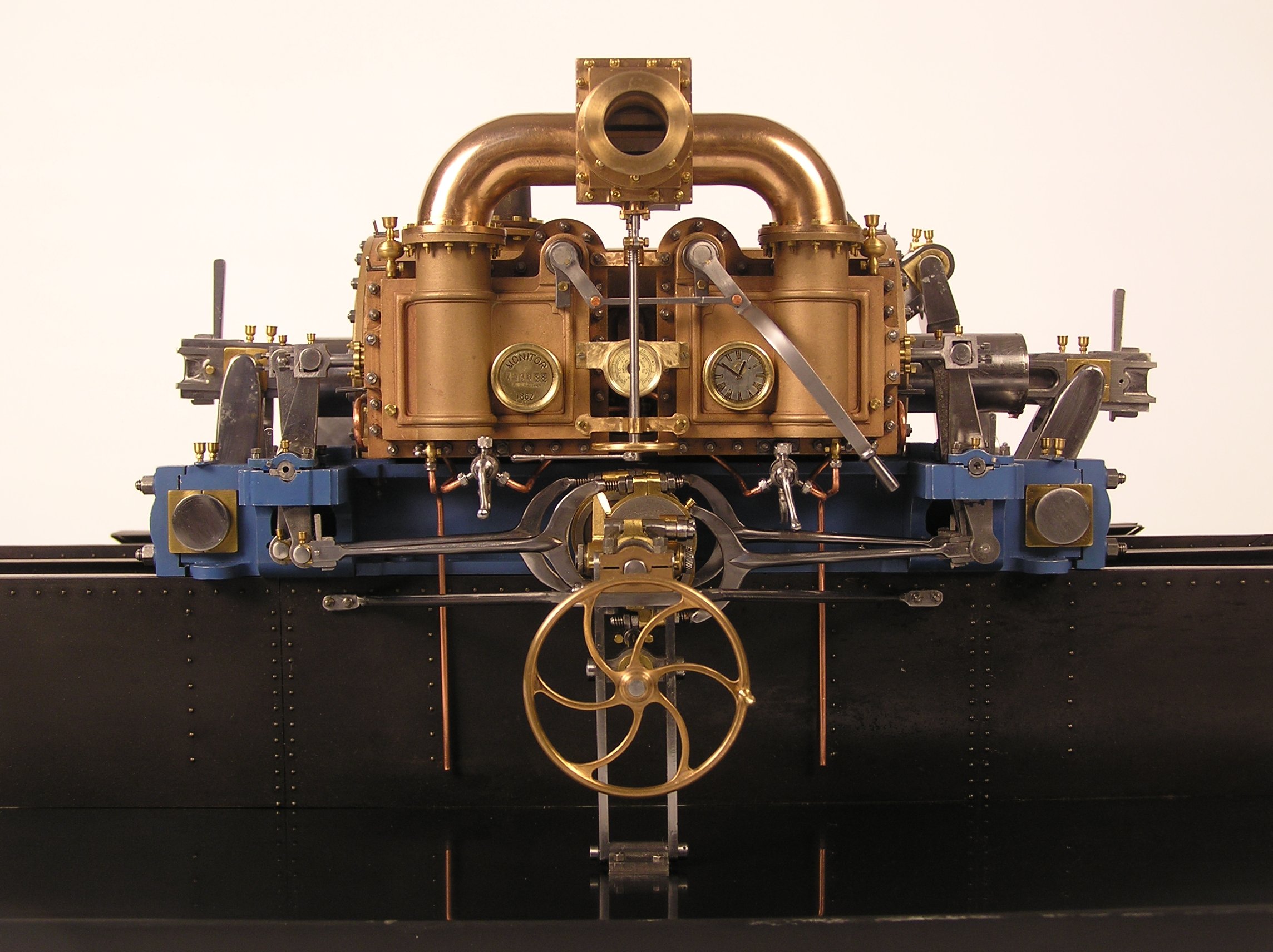
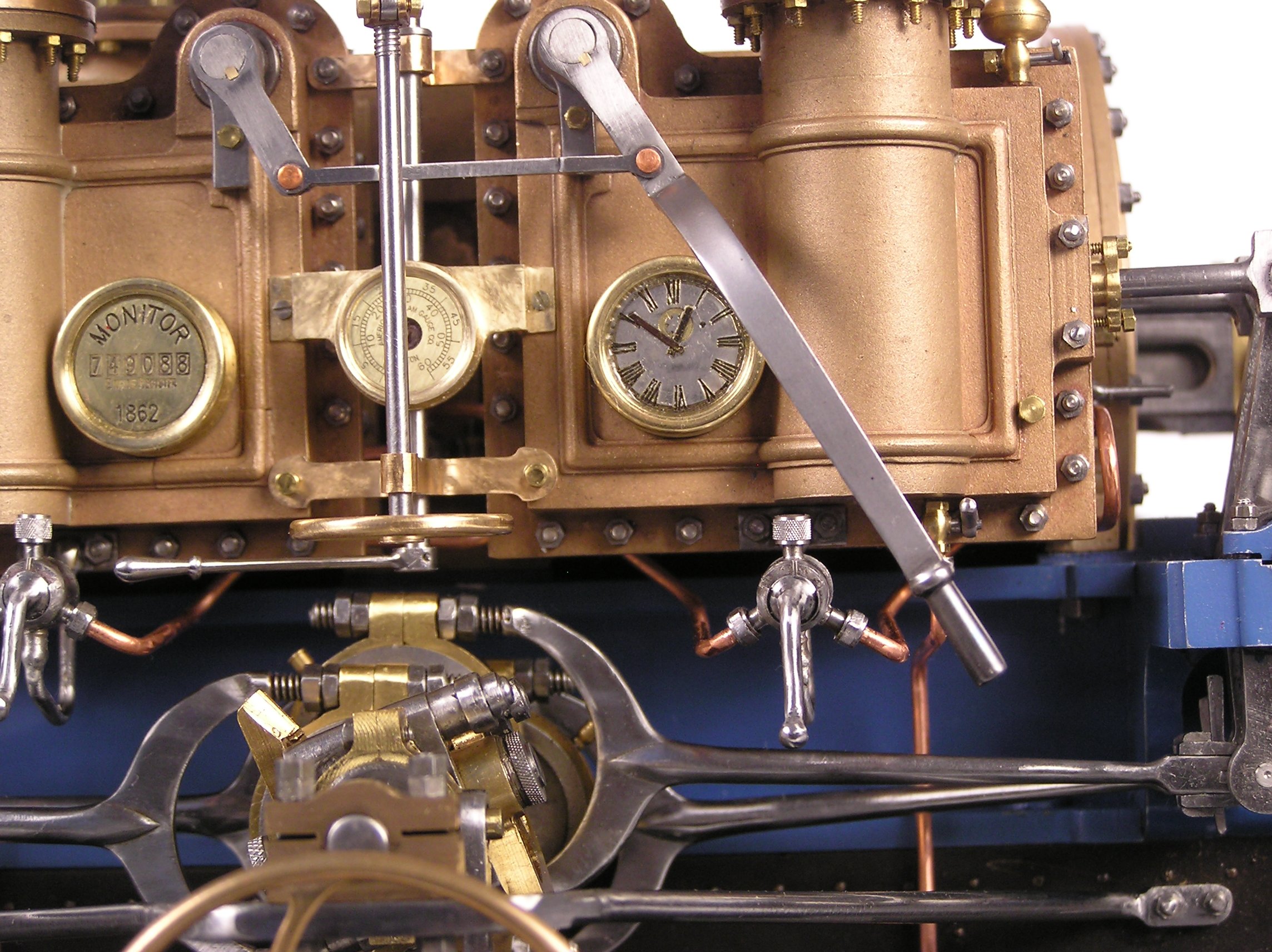
Engineers View
|
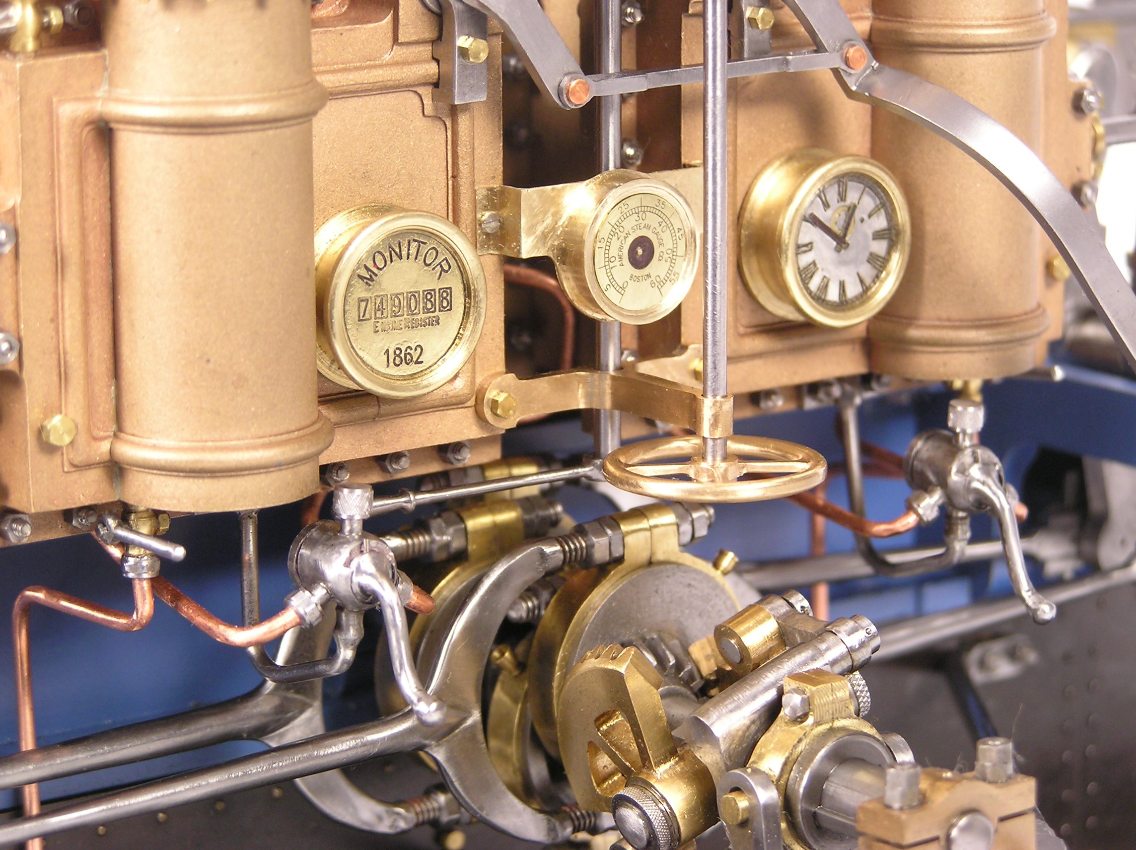
Gauges L to R
Turns log, Steam, Time |
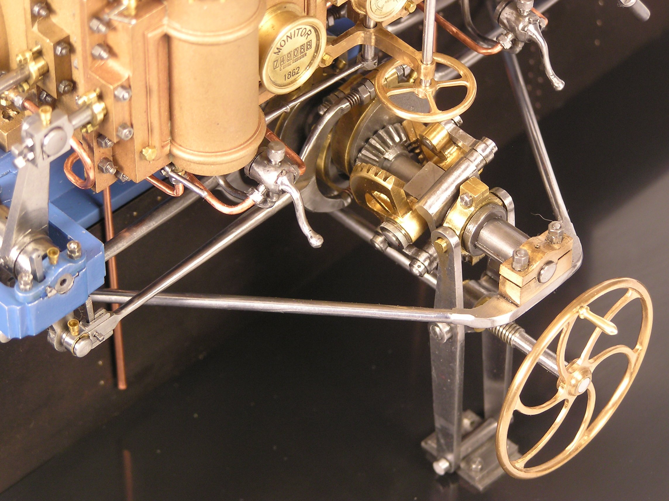
Reversing Wheel
and Gears |
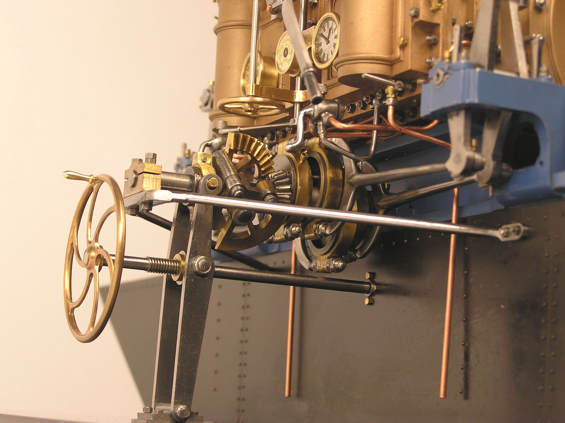
Reversing Shaft
and Eccentrics |
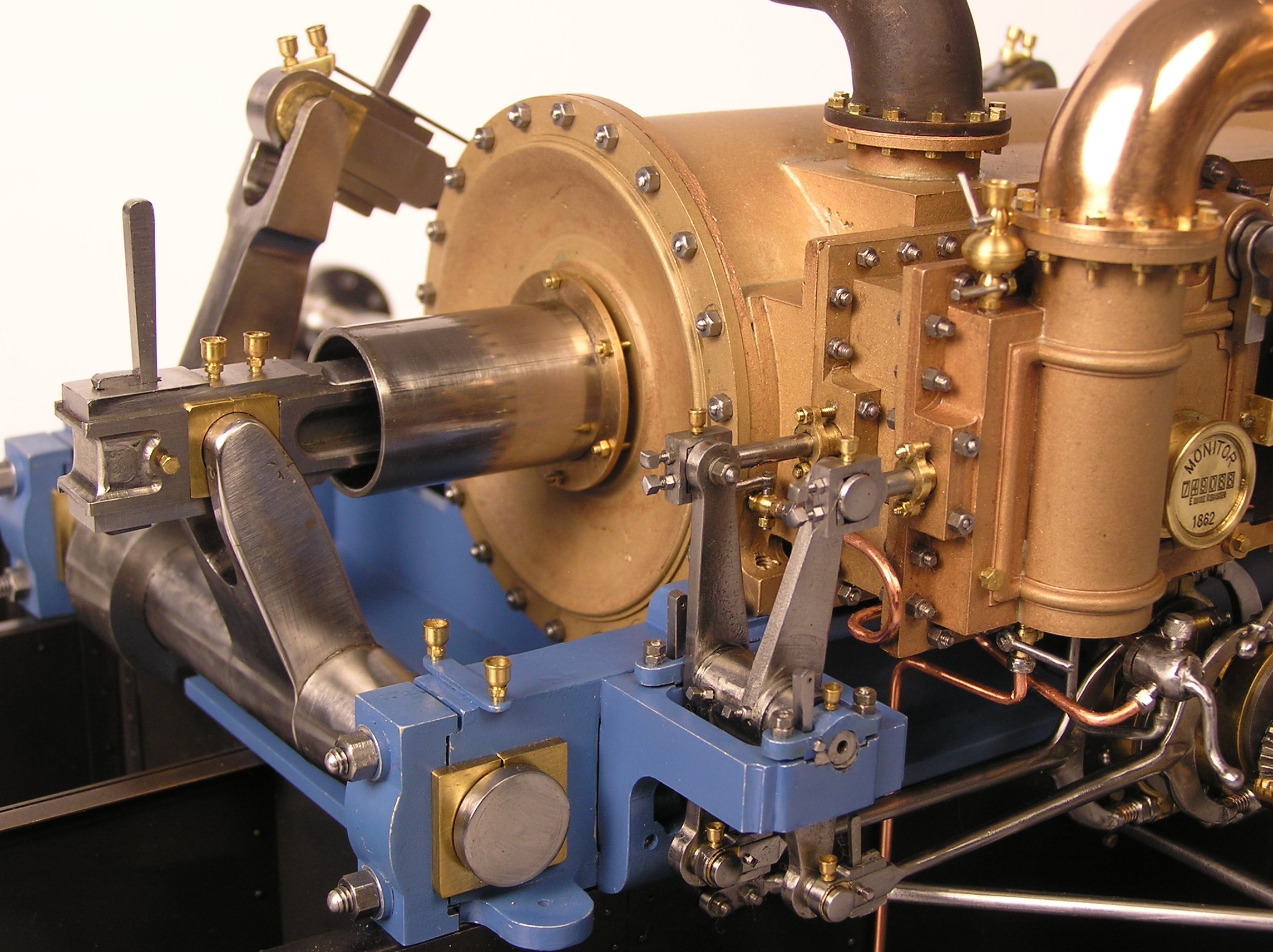
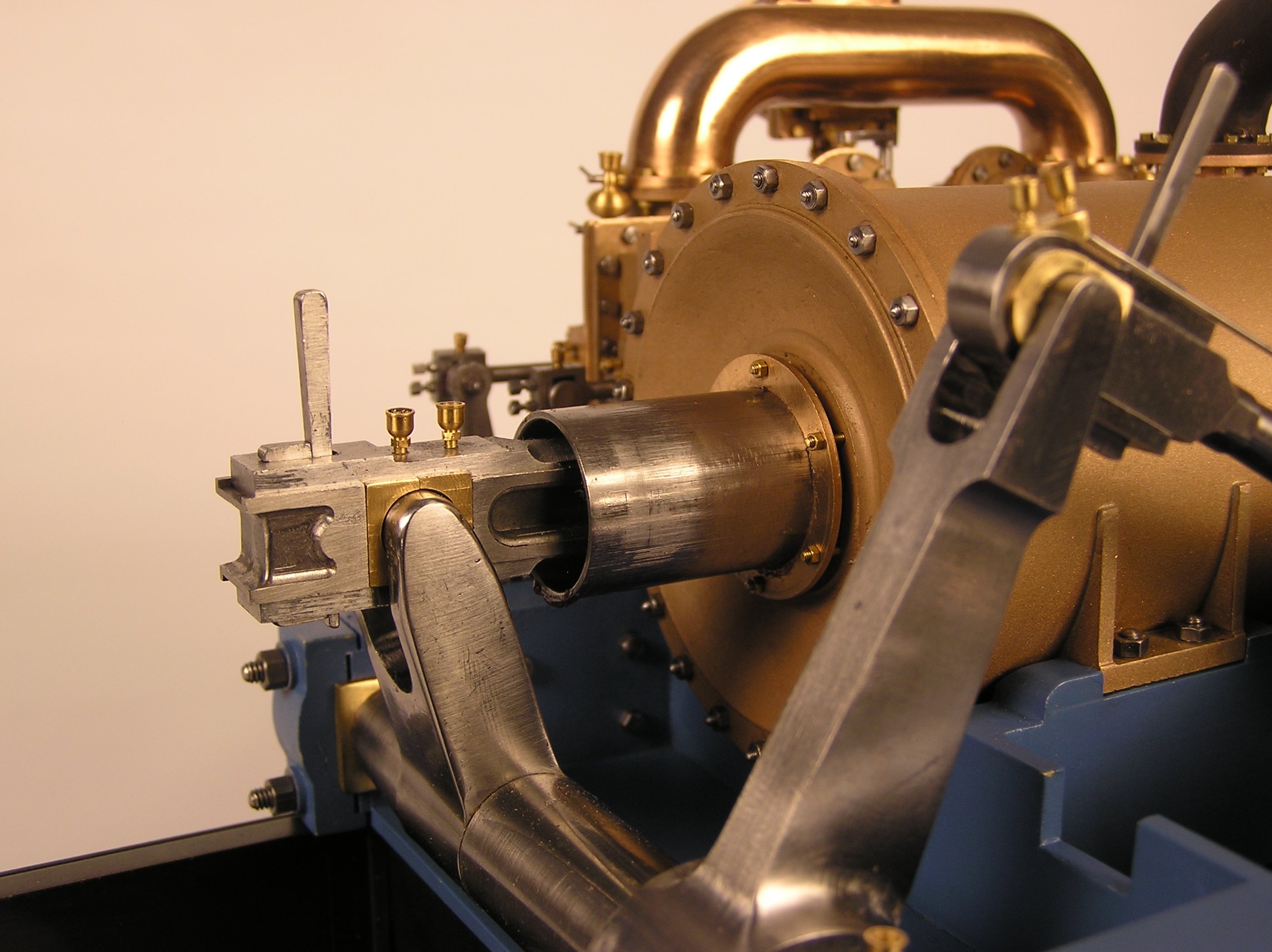
Translator Levers
Piston Rod within Trunk |
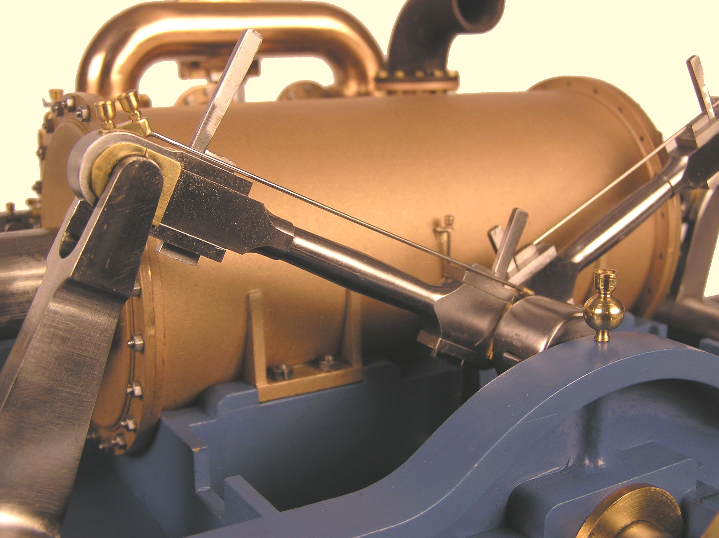
Vibrating Lever Shaft
( Rock Shaft ) |
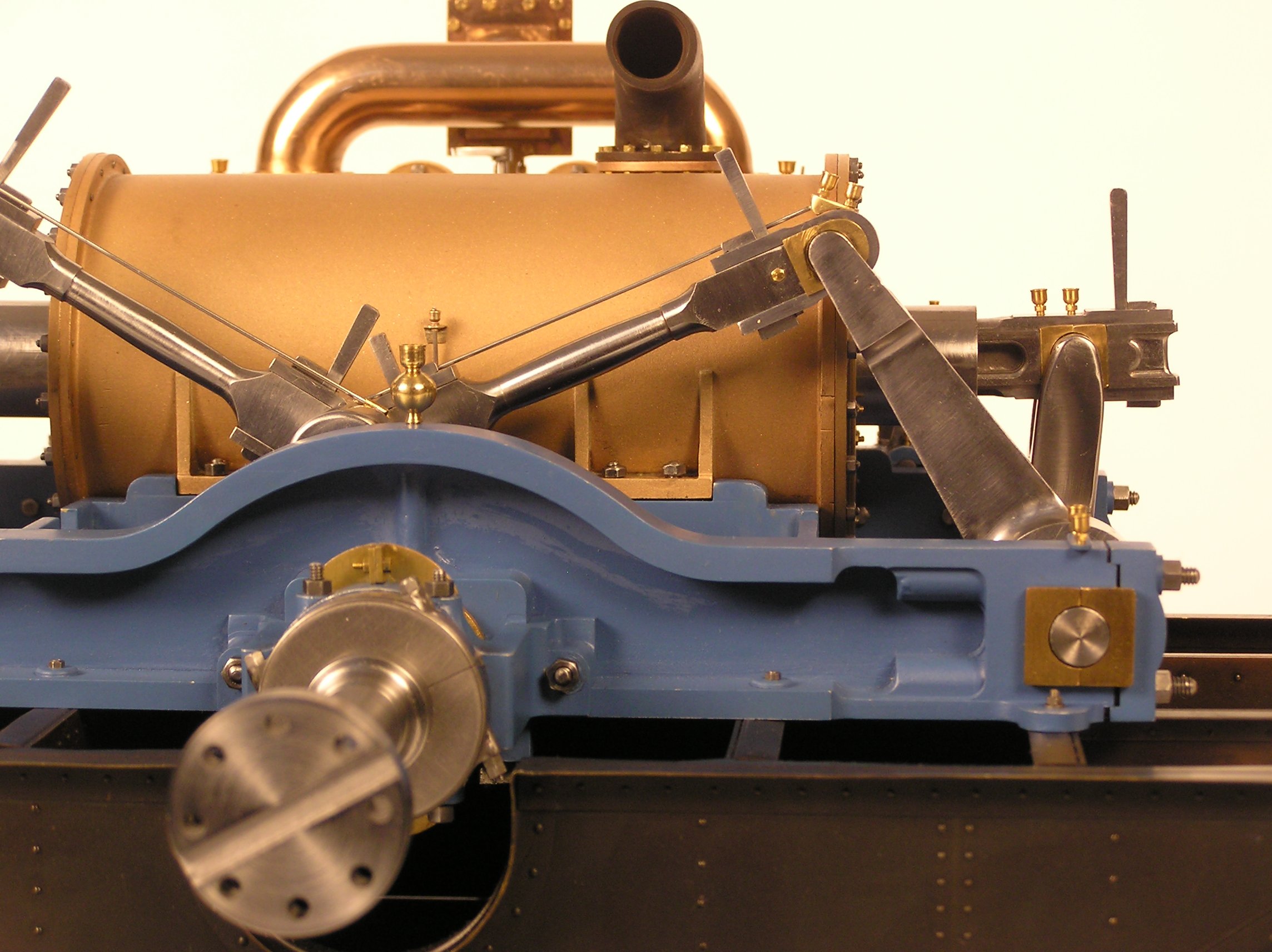
Main Connecting Rods
and Vibrating Lever |
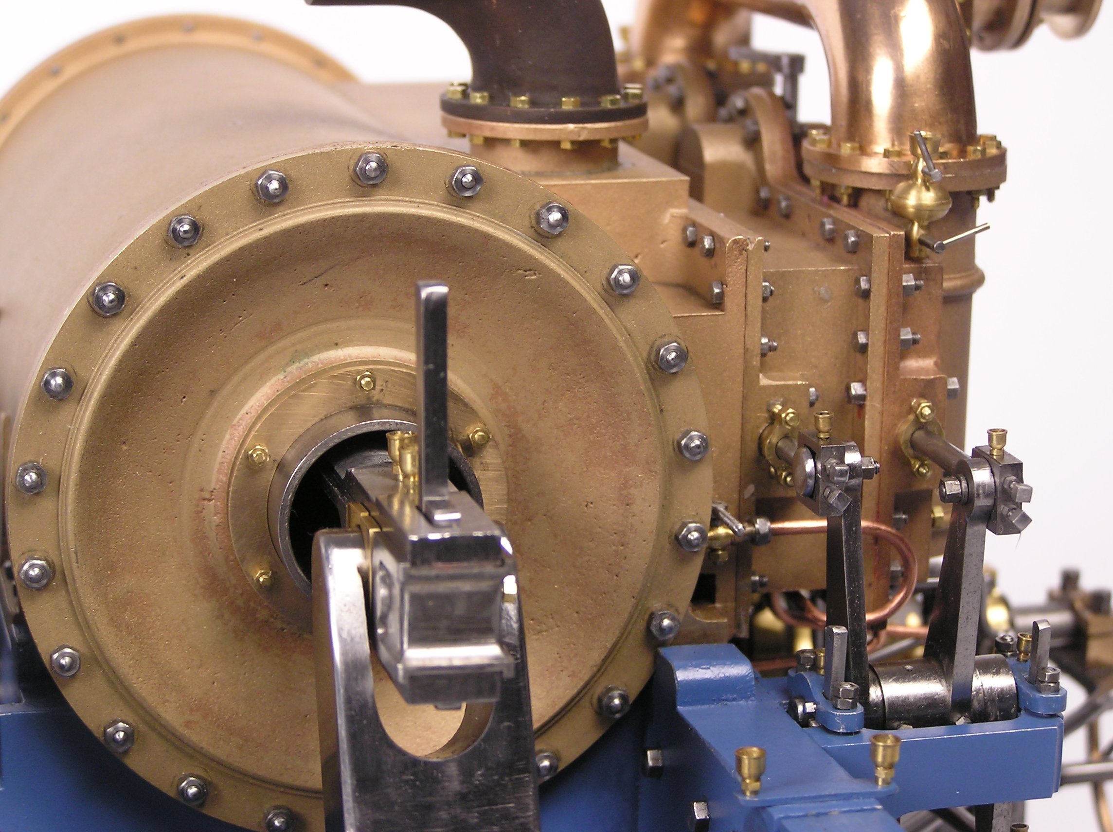
Propeller Shaft Crank
and Main Rods |
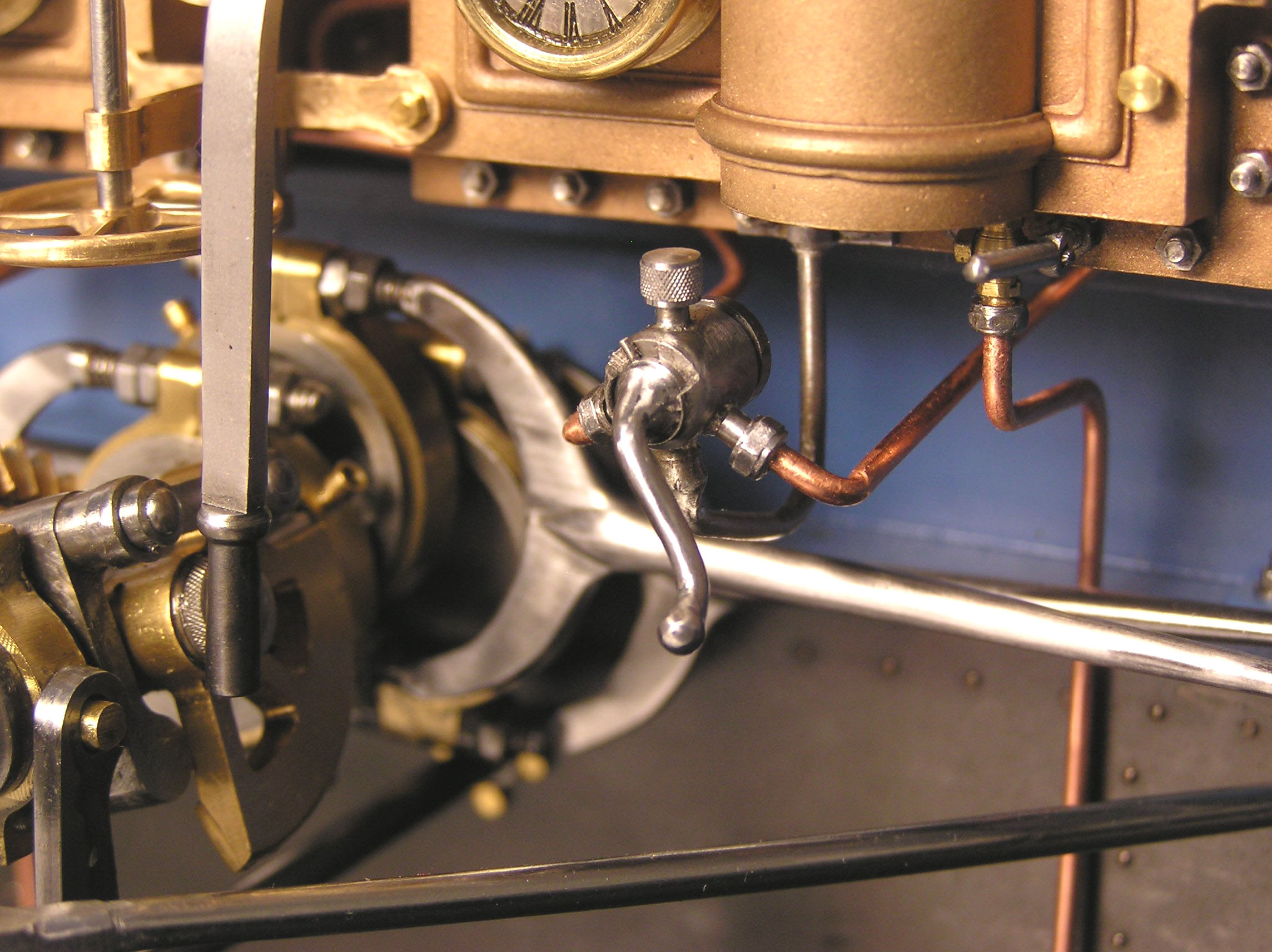
3 Way Cock
for Indicator |
Cutoff Chest
with Control Arm |
Starboard Cutoff
Main Steam Chest |
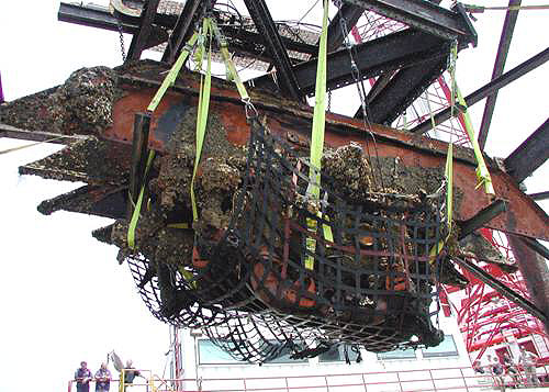
Engine Recovery 2002
NOAA Photo |
Copyright © 2005 - 2024
Richard Carlstedt All rights reserved.
Richard Carlstedt All rights reserved.
Model Steam Engines